How to wire the digital display instrument
How to wire the digital display instrument
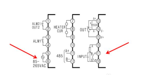
Taking this wiring diagram as an example, let's first look at the power supply and sensor connections. Pins 5 and 6 are for power supply (AC 85-265V), while pins 16, 17, and 18 are for sensor connections. For thermocouples (K, E, J, etc.), connect the positive wire to pin 18 and the negative wire to pin 17. For thermal resistors (PT100, CU50), connect pin 16A to one wire, and pins 17B and 18B to the other wire. If PT100 has only 2 wires, short-circuit pins 17 and 18.

Next, let's look at the heating output and alarm output. According to this diagram, OUT1 represents the heating output. If it is a relay output, connect the heating element to pins 14 and 15. If it is an SSR (Solid State Relay) output, connect pin 13+ to the positive side and pin 14- to the negative side. If it is an analog output (4-20mA, 0-10V, etc.), connect the current output to pins 13+ and 14-, and the voltage output to pins 15+ and 14-. ALM1 and ALM2 represent alarm outputs. Connect alarm 1 to pins 3 and 4, and alarm 2 to pins 1 and 2. The alarm mode and deviation values can be adjusted through internal parameters.
Finally, let's look at the remaining current detection and RS485 communication functions. This meter can connect two current transformers to detect the current in the heating system. Pins 7, 8, and 9 are for the current detection, with pin 8 as the common terminal. Pins 11 and 12 are for RS485 communication, where pin 11 is for A+ and pin 12 is for B-. This allows remote monitoring and temperature adjustment.
 English
What is a Digital Panel Meter?
A digital panel meter (DPM) is an electronic instrument used to measure and display various electrical parameters such as voltage, current, frequency, temperature, and other physical quantities. Unlike analog meters, which use a dial or needle to indicate measurements, a digital panel meter presents the reading in a numeric format, typically on an LED or LCD screen.
Read MoreWhat is the meaning of PFE in electrical engineering?
In the field of electrical engineering, PFE (Partial Discharge Free Energy) is an important concept related to the performance of electrical equipment, especially the insulation system. Partial discharge refers to the electrical discharge phenomenon caused by the electric field strength locally exceeding the insulation strength in the insulating material of the electrical equipment.
Read MorePassive PFC vs Active PFC
Passive PFC uses passive components such as inductors and capacitors. It works by shaping the input current waveform to be more in - phase with the input voltage waveform. A simple inductor - capacitor (LC) circuit is often used. The inductor stores and releases energy to reduce the phase difference between current and voltage. However, its ability to correct the power factor is relatively limited. It usually provides a power factor correction in the range of 0.7 - 0.8.
Read More