DDKJ - Mastering Soldering Iron Temperature Control: Ensuring Quality and Safety in Welding
DDKJ - Mastering Soldering Iron Temperature Control: Ensuring Quality and Safety in Welding
DDKJ - Mastering Soldering Iron Temperature Control: Ensuring Quality and Safety in Welding
Soldering is a crucial process in electronic manufacturing and repair, and mastering the correct temperature of the soldering iron is fundamental for achieving high-quality solder joints. Improper temperature control can not only affect product reliability but also cause component damage or safety issues.
This article will discuss how to control soldering iron temperature, the soldering temperature requirements for different materials and components, and the problems that can arise from excessive temperature.

1. How to Control Temperature
Proper temperature control begins with selecting the right tools and settings. A soldering iron with temperature adjustment capabilities is the ideal choice, allowing operators to adapt the temperature according to the different soldering materials and components. Additionally, the following points are also very important:
- Preheating: Ensure the soldering iron is fully preheated to the set temperature to guarantee stability when soldering begins.
- Calibration: Regularly calibrate the soldering iron's temperature settings to address any deviations, especially after extended use.
- Cleaning: Keep the soldering iron tip clean, as oxidation and contaminants can affect heat transfer efficiency.
- Monitoring: Regularly check the actual temperature using a thermal imager or a dedicated soldering iron temperature tester to ensure accuracy.

2. Soldering Temperature Requirements for Different Materials and Components
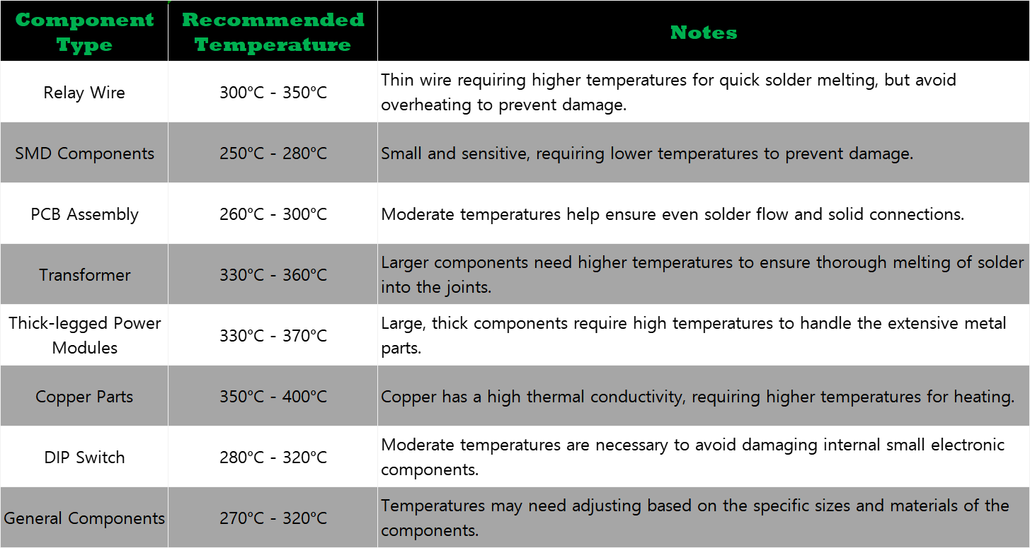
The table below lists the recommended temperature ranges for soldering various common materials and components:

3. Problems Caused by Excessive Temperature

Setting the temperature too high can lead to a variety of problems that affect both the quality of the soldering and safety, including:
- Weak Solder Joints: Excessively high temperatures can cause solder to flow too much, resulting in cold solder joints.
- PCB Damage: High temperatures can cause thermal damage to PCB materials, such as delamination of copper layers or warping of the substrate.
- Component Damage: Sensitive electronic components can be damaged by high temperatures, affecting device functionality.
- Health Risks: Higher temperatures exacerbate the oxidation of solder and flux, increasing the release of harmful gases.
In conclusion, precise control of the soldering iron temperature is crucial for ensuring product quality and operational safety in soldering tasks. At Dadao Electric Co., Ltd. (DDKJ), we strictly control the temperature of the soldering iron, reducing quality issues from the source and protecting the safety of operators.
 English
What is a Digital Panel Meter?
A digital panel meter (DPM) is an electronic instrument used to measure and display various electrical parameters such as voltage, current, frequency, temperature, and other physical quantities. Unlike analog meters, which use a dial or needle to indicate measurements, a digital panel meter presents the reading in a numeric format, typically on an LED or LCD screen.
Read MoreWhat is the meaning of PFE in electrical engineering?
In the field of electrical engineering, PFE (Partial Discharge Free Energy) is an important concept related to the performance of electrical equipment, especially the insulation system. Partial discharge refers to the electrical discharge phenomenon caused by the electric field strength locally exceeding the insulation strength in the insulating material of the electrical equipment.
Read MorePassive PFC vs Active PFC
Passive PFC uses passive components such as inductors and capacitors. It works by shaping the input current waveform to be more in - phase with the input voltage waveform. A simple inductor - capacitor (LC) circuit is often used. The inductor stores and releases energy to reduce the phase difference between current and voltage. However, its ability to correct the power factor is relatively limited. It usually provides a power factor correction in the range of 0.7 - 0.8.
Read More